
Place Luminaires to Meet IES Criteria
In the next few steps, we will use several different tools in AGi32 to help us place the luminaires.
- Set AGi32 in the “Direct Only – AutoCalc On” mode from the Calculate menu.

- Click on the Design Isolines button (bottom of screen).
This is a real-time direct light calculation we can use to help us determine pole location and spacing.

We will set a single isoline contour value based on our design Minimum illuminance level. Recall this is 5 lux. We’ll call if 0.5 footcandles (knowing we have some fudge as it’s really 0.46!).
- Enter 0.5 in the red cell
- Check the box to Consider Surface Obstruction
- Click OK to exit the dialog.
- Set the cursor Snap to 1.
- Turn OFF the SnapTo button.
We are now ready to place some poles in the project.
- In the Luminaire Toolkit, set the MH cell to 27.5’ corresponding to a 25’ pole and 2.5’ concrete base.
- Select the Label B luminaire from the menu
- Click on the Locate button (we are placing at Orient=0 as set in toolkit by default).
- Drag the pole to the lower left corner of the parking lot. Watch the interaction of the .5 fc contour with the left edge of the property. When you find the best position (about X=170), click the mouse to drop a pole.

Notice the Design Isoline remains active.
- Move along the parking median and watch the contour interaction with the bottom edge of the lot. When you can barely see the contour between the two poles you have the appropriate spacing between poles that can be repeated throughout the lot.
- The command line (bottom left of AGi32 screen) will tell you the distance from the last pole. It should be about 90’. Click to drop a pole there.

Notice we could continue in this way to place poles. However, for this lot, we have what we need to know to use a different command.
- Right click to terminate the placement command. (notice our results are computed for two poles)
Magnify the Symbol
In most site lighting scenarios, you will find the true size symbol is too small to easily see. AGi32 allows you to “magnify” the symbol for easier workflow. This does not change the physical size; it’s a visual tool only.
- Click on the Magnify Symbol command in the luminaire Toolkit.
- Set the magnification level to 3.

Array the poles
Now let’s fill out the parking lot with poles. The easiest way to do this is using an “Array”.
- Turn Off the Ortho command (F8)
- From the Luminaire Toolkit, click on the Array command.
- Enter “Set Spacing” of 90 x 120. (We know the parking medians are 120’ apart, standard size, but we could have measured).
- When you click OK to exit the Array dialog, the software now expects you to select a luminaire to begin the array. Select the second luminaire we placed.

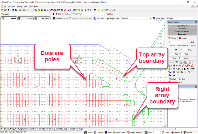
- Drag the cursor in the X direction (across the lot) and notice the little dots where the poles will be (90’ apart).
- Click the mouse at approximately X=850, in the right most median setting the X boundary of the array.
- The array command is still active, move the cursor upwards until you see the second row of dots, two driving lanes up. Click the mouse again and the luminaires will be in place.
- Click on the Plan View icon or Zoom Extents icon on the top toolbar. We have some adjusting to do.
- Use the Move Luminaire command to move the right most pole to the median.
- Click on the command, select the luminaire, select a point to move from (luminaire position is easiest), then move to new location and click.

Notice the points are calculated! This is the Autocalc feature, it computes at the conclusion of each command.

- If Design Isolines are off, turn them back on by clicking the button. Notice we have a new void in lighting the drive lane.

Use the delete Luminaire command to remove the location that conflicts with the building.
- Click the command, click the luminaire, right click.

We now have a sizable void on the upper left area as well.

With Design Isolines enabled add single-head poles to the void areas. There are two methods to do this, select one and carry out the action.
- Method one: Set the toolbar to Label A, enter an Orient angle of 270 (facing south), click the Locate button.
- Method two: Set the toolbar to Label A, use the Locate & Orient option to place the luminaires. The first click drops the pole, the second sets the horizontal Orient angle.

The upper right area presents a significant challenge, as does the driving lane on the right side. Can you fix this?

Possibilities include:
Add single luminaires (A)
Add or relocate two-headed (B)
Adjust mounting height
In this case, if we change the mounting height to 30’ (27.5’ pole, 2.5’ base), the layout works nicely. This allows us to increase the pole spacing from 90’ to 96’ and now the right side of the lot is covered. These are precisely the types of decisions you are faced with regularly.
We can male these changes as follows:
- Delete all of the Label B luminaires except the left most location (Delete window).
- Use the Edit Luminaire command to change the mounting height of all three remaining luminaires (Bulk edit, change MH).
- Turn on Design Isolines.
- Use the Copy command to create a copy of the existing Label B luminaire. Check spacing as we did previously. Drop it at 96’.
- Use the Array command to create a 96x120 array.
- Delete the extra pole in the building (upper left), (delete single).
- Move the one single head (A) to the right to align with new layout (Move single).
Now enable the Static Isolines (this is different than Design Isolines we have been using).
- From the Calculations Toolkit, click on the Isolines button.
- Select contours of 0.25 and 0.5. in blue and red colors, respectively.
- Enable the lines with the checkbox.

Our layout now looks like this:

 RESCUE
Open the file: RESCUE-Parking-3.agi.

